Simple Sinewave Inverter Circuits – Making Easy Circuits
Let''s try to work out the proposed simple 500VA Pure Sine Wave inverter circuit layout elaborately with the following facts:IC2 and IC3 are in
Let''s try to work out the proposed simple 500VA Pure Sine Wave inverter circuit layout elaborately with the following facts:IC2 and IC3 are in
Let''s try to work out the proposed simple 500VA Pure Sine Wave inverter circuit layout elaborately with the following facts:IC2 and IC3 are in particular designed in the form of the PWM
Here, we designed a simple sine wave inverter circuit that produces 50Hz quasi-sine wave output using a single IC CD4047 and some discrete components, which makes it a very cost
Analog | Embedded processing | Semiconductor company | TI
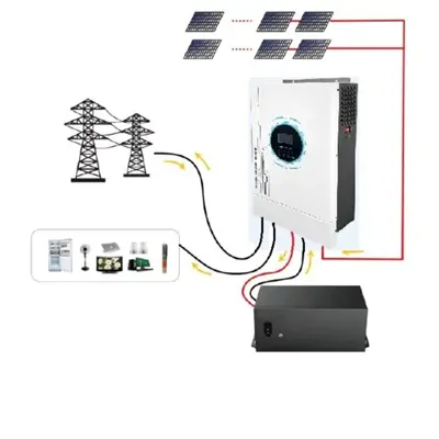
In this article, we will discuss how to use a push-pull converter, sinusoidal pulse width modulation, an H-bridge, and a low-pass LC filter to create a pure sine wave inverter circuit diagram.
Learn how to design a pure sine wave inverter circuit using the sg3525 IC. This detailed circuit diagram will help you build your own inverter.
How to make a full sinusoidal inverter using the EGS002 driver board. Supplied with 12V from a battery and output 230V AC at 50Hz with SINE wave and 500W.
Pure Sine wave inverter consist of a microcontroller unit which generates a switching signal of 15 KHz, an H-bridge circuit to convert the signal into AC, a low pass LC filter circuit to block
In this article I have explained comprehensively regarding how to design a sine wave inverter without any form of coding or complex circuit designs. The included designs are simple yet
With this novel inverter design, an Arduino Nano replaces a lot of hardware, resulting in a simple pure sinewave inverter circuit. Find this and other hardware projects on Hackster.io.
Here, we designed a simple sine wave inverter circuit that produces 50Hz quasi-sine wave output using a single IC CD4047 and some discrete
Build a low cost 12V to 220V (DC-AC) Pure Sine Wave Inverter from scratch! The project is based on the low cost EGS002 SPWM driver board module. The DIY inverter board can handle up to 1kW
The primary objective of designing this Arduino based power inverter is to design a low cost inverter as compared to the existing expansive inverter available in the market.
PDF includes complete article with source references.
Download solar street light datasheets, pricing guides, and custom specification templates.
15 Galaxy Avenue, Linbro Business Park
Sandton, Johannesburg, 2065
ZA: +27 11 568 4021
EU (Germany): +49 89 4520 8912
Mon-Fri: 8:30 AM – 5:30 PM (SAST / CET)